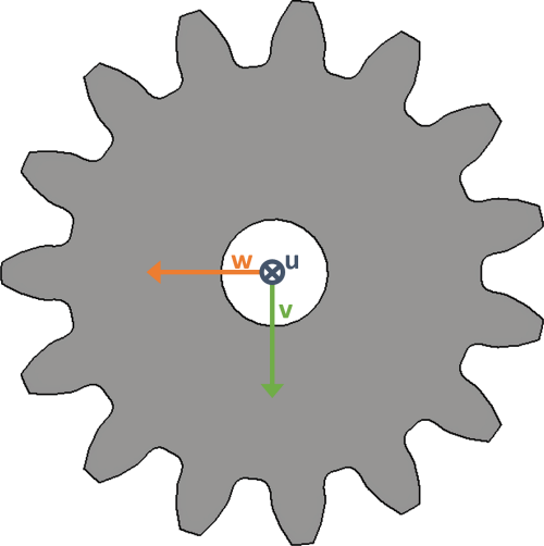
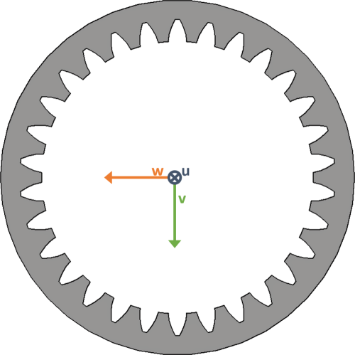
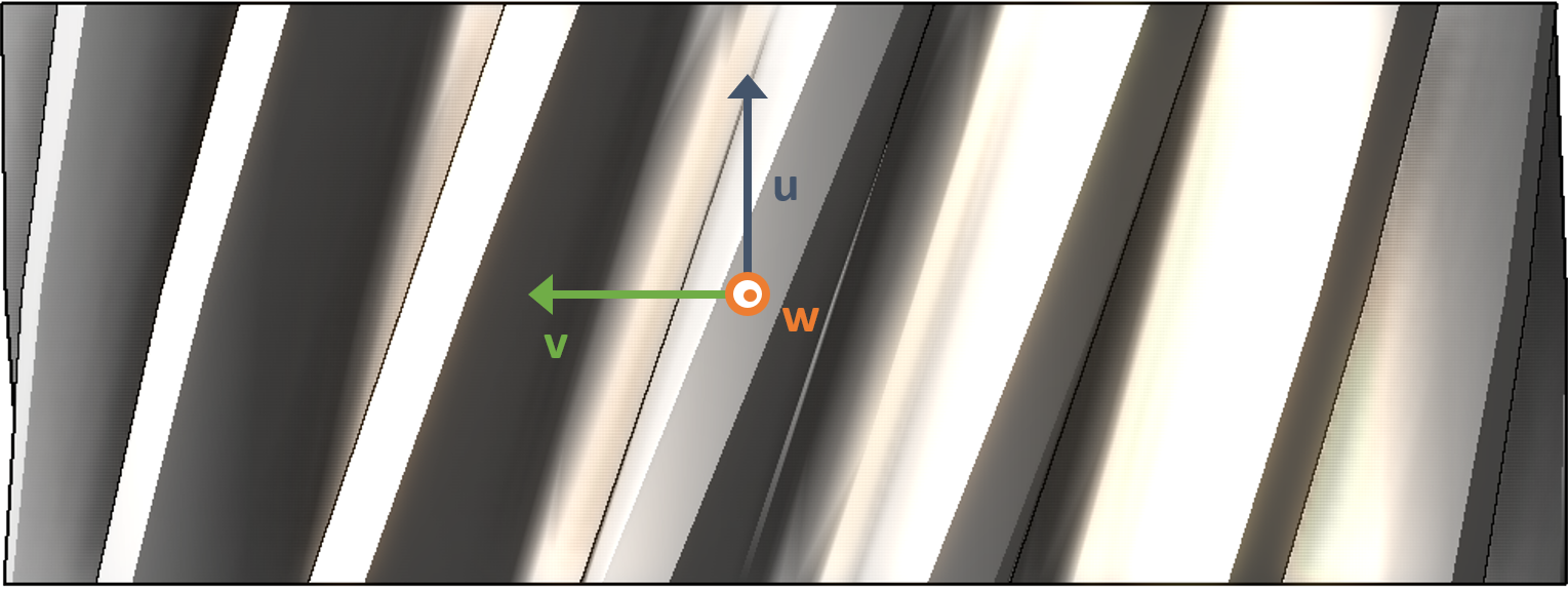
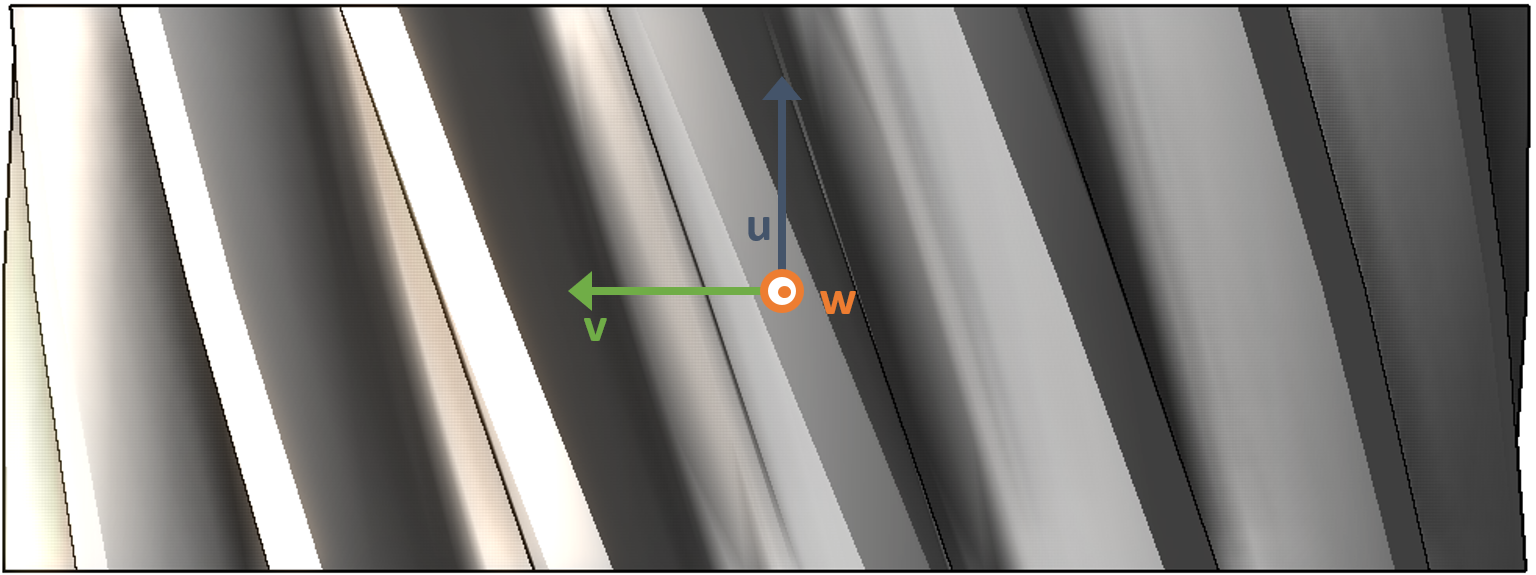
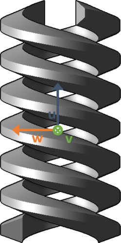
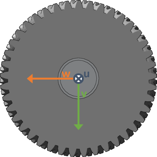
Local coordinate system for all components
The position and orientation of the local coordinate system (if available) for each component type is defined in this section.
Terminology
Term | Definition |
|---|---|
End point | Each component has two end points. These are the points with the maximum axial distance from one another when the component is projected onto the shaft axis. One of these end points will be defined as the left end point, the other as the right end point. |
Total width | The axial distance between the two end points. |
Midpoint | The point on the shaft axis halfway between the two end points. |
Midpoint plane | The plane which includes the midpoint and is perpendicular to the shaft axis. |
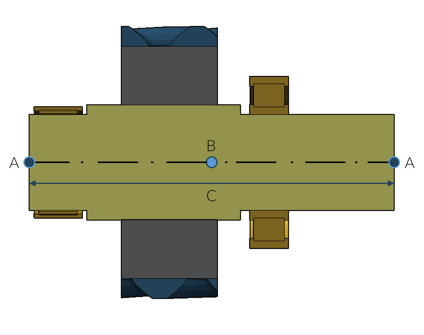
A: End points, B: Midpoint, C: Total width
Definition of the u-axis
Component | Definition of the u-axis |
|---|---|
All component types | The u-axis runs along the direct shaft axis from the left to the right side of a component. |
Definition of the v- and w-axes
Component | Definition of the v and w-axes | ||||
|---|---|---|---|---|---|
shaft | Not specified, as a shaft is generally rotationally symmetrical. The sections that make up a shaft are lined up in order along the u-axis. 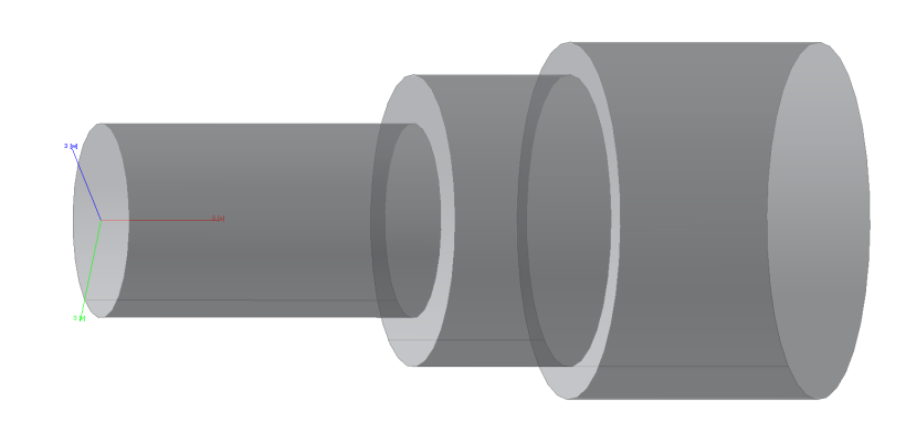 | ||||
cylindrical_gear ring_gear | The w-axis points to the midpoint of the first tooth in the midpoint plane. The datum_face_orientation attribute indicates whether the datum face is in the positive or negative direction with respect to the local coordinate system of the gear.
| ||||
bevel_gear | The w-axis points toward the center point of the first tooth in the plane perpendicular to the shaft axis. The bevel_cone_orientation attribute specifies whether the bevel tip lies in a positive or negative direction relative to the local coordinate system of the bevel gear. 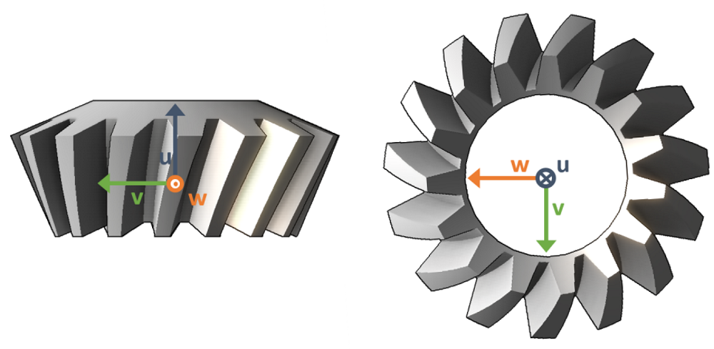 | ||||
worm_gear worm_wheel | The w-axis points toward the center point of the first tooth in the plane perpendicular to the shaft axis.
 | ||||
rolling_bearing_with_catalog_data rolling_bearing_with_detailed_data | The angular_position_around_u attribute is used to specify the angular position of the rolling elements. The angle is counted from the v-axis. See position_of_rolling_elements. 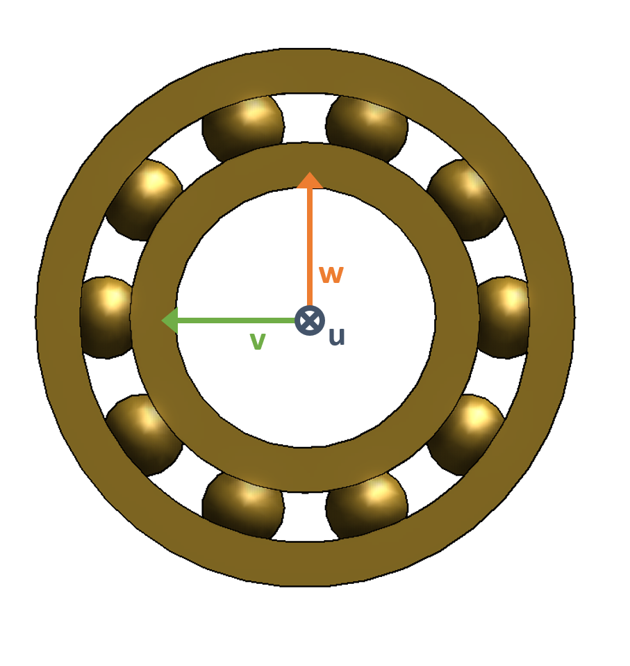 |
Position of the coordinate origin
Component | Position of the coordinate origin |
|---|---|
shaft side_plate | The origin of the local coordinate system is the left end point. |
bevel_gear | The origin of the local coordinate system corresponds to the projection of the design point P on the gear axis. For bevel gear stages without axial offset, the design point is located at a height equal to half of the width of the gear (ISO 23509 2006 A.3). For hypoids, there are multiple methods for selecting the design point; therefore, the position of the design point may differ from the center of the tooth width; see ISO 23509 2006 A.3 for details. Deviations from the tooth center arise for both gears when using method 1 (Gleason) as well as for the pinion when using method 3 (Klingelnberg). |
All other component types | The origin of a component is its midpoint. |
