Gears
Gear types
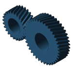 | 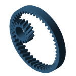 | 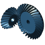 | 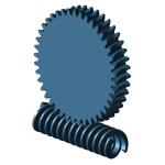 |
This section describes assemblies that represent two meshed gears. Planetary stages are addressed in a separate section. There are several types of stages that are modeled in a similar fashion:
Cylindrical gear stages (cylindrical_stage)
Bevel gear stages (bevel_stage)
Worm stages
Not yet precisely specified:
Cross helical stages
Abstract general_stage and general_gear components have been introduced to standardize the description of the modeling.
Everything related to these components in this section applies for the following component combinations:
cylindrical_stage, cylindrical_gear, cylindrical_gear
cylindrical_stage, cylindrical_gear, ring_gear
bevel_stage, bevel_gear, bevel_gear
worm_stage, worm_gear, worm_wheel
A cylindrical gear stage consists of:
1 stage component (general_stage)
2 gears (general_gear)
and is connected to the gear_unit via an assembly relation.
Required components | XML syntax |
|---|---|
general_stage | <component id="3" type="general_stage">... </component> |
general_gear | <component id="6" type="general_gear"> ... </component> |
general_gear | <component id="7" type="general_gear"> ... </component> |
shaft | <component id="4" type="shaft"> ... </component> |
shaft | <component id="5" type="shaft"> ... </component> |
Required relations | XML syntax |
|---|---|
Stage relation Stage - gear1 - gear2 | <relation id="2" type="stage"> <ref id="3" role="stage" hint="general_stage"/> <ref id="6" role="gear_1" hint="general_gear"/> <ref id="7" role="gear_2" hint="general_gear"/> </relation> |
Assembly relation Shaft1 - gear1 | <relation id="3" type="assembly"> <ref id="4" role="assembly" hint="shaft"/> <ref id="6" role="part" hint="general_gear"/> </relation> |
Assembly relation Shaft2 - gear2 | <relation id="4" type="assembly"> <ref id="5" role="assembly" hint="shaft"/> <ref id="7" role="part" hint="general_gear"/> </relation> |
Assembly relation Gear unit - stage | <relation id="5" type="assembly"> <ref id="1" role="assembly" hint="gear_unit"/> <ref id="3" role="part" hint="general_stage"/> </relation> |
Example - model of a cylindrical gear stage (cylindrical_stage)
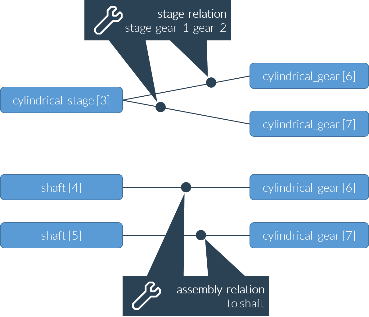
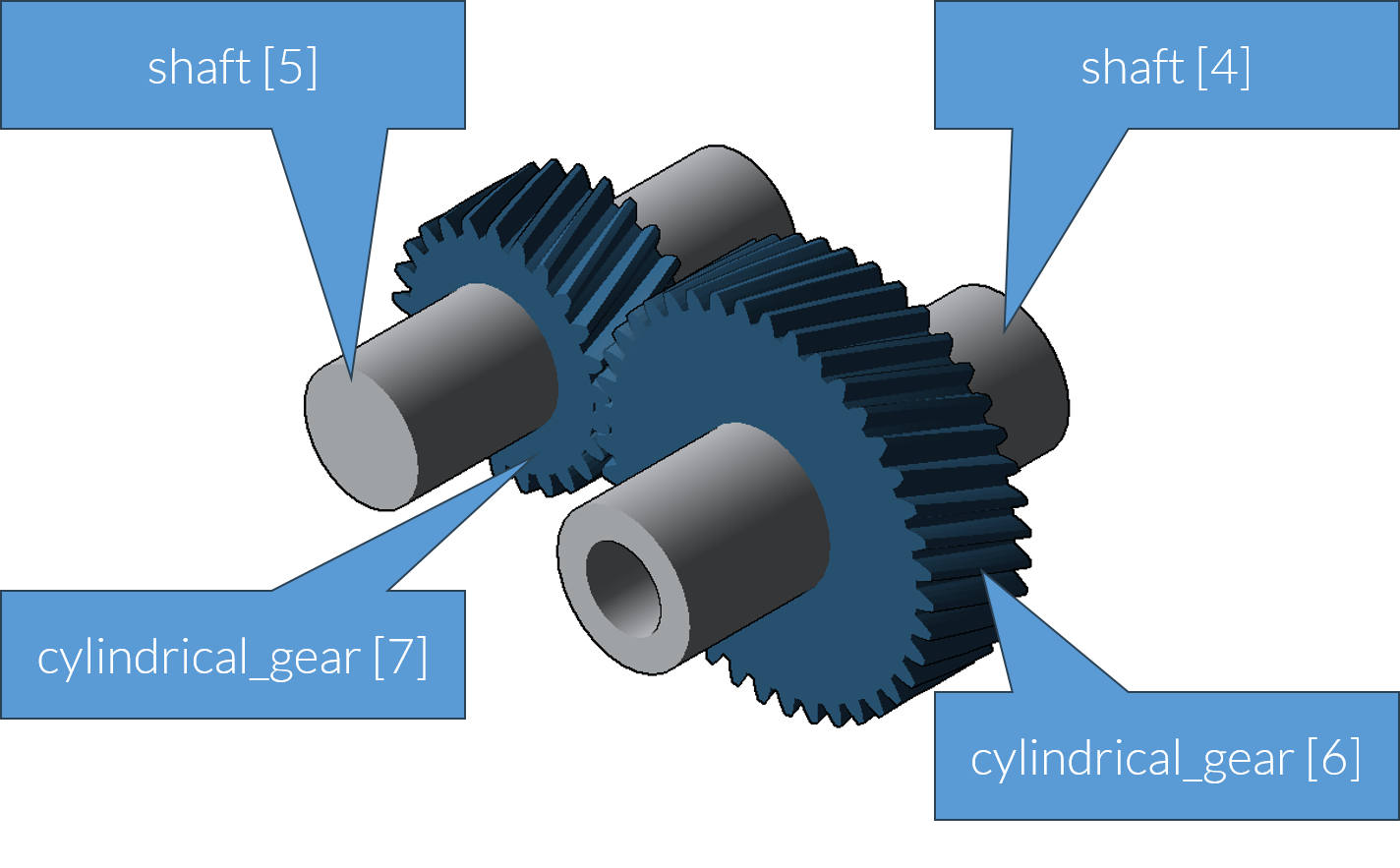
Internal and external gears (cylindrical gear stage)
A cylindrical gear stage can either describe the meshing of two external gears (cylindrical_gear) or an external gear with an internal gear (ring_gear). An internal gear is referred to as a ring gear. The ring_gear includes all the attributes of a cylindrical_gear and behaves like a cylindrical_gear in all relations.
Note: There are no special conventions for ring gear attributes; they use the same validity ranges as an external gear (number of teeth, etc. are positive values). Refer to the descriptions of the individual attributes for details.
Example - model of a bevel gear stage (bevel_stage)
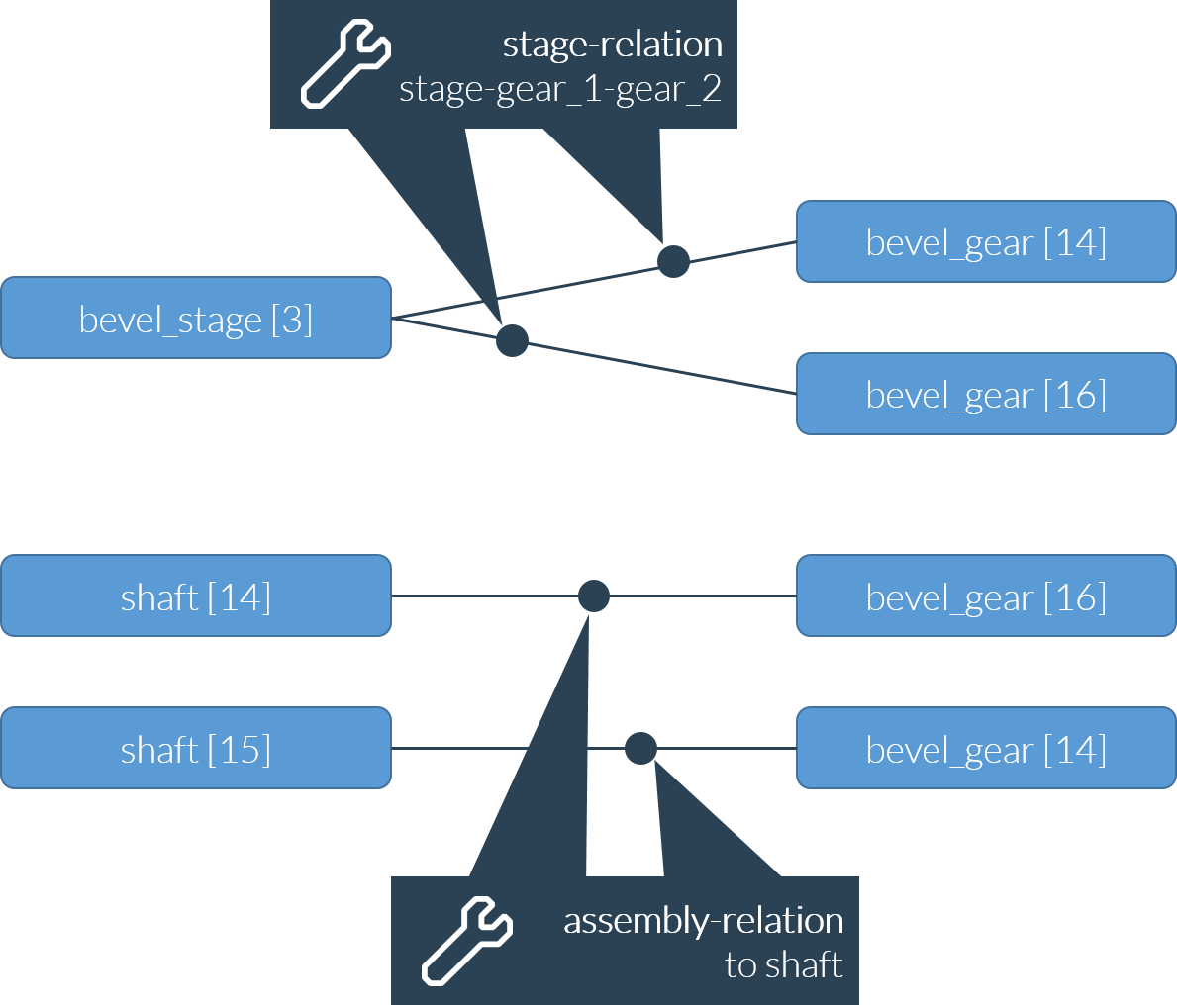
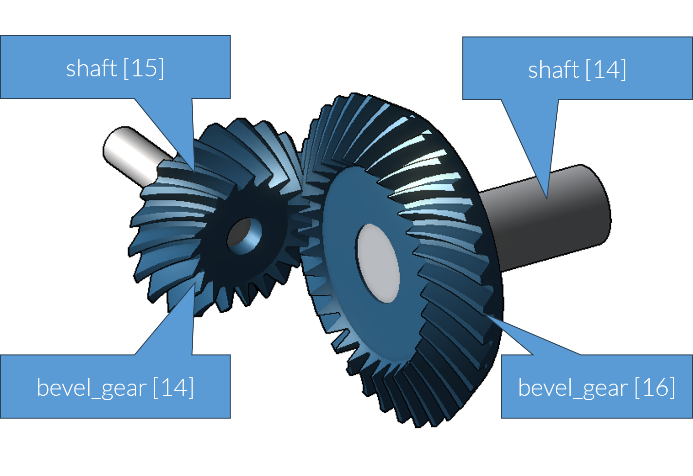
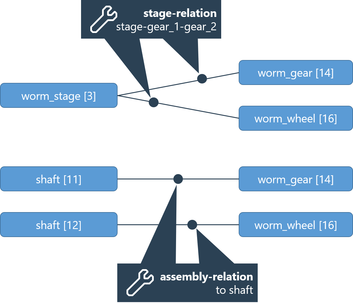
Example - model of a worm gear stage (worm_stage)
Mesh-related gear data
Many parameters of a gear are mesh-related, which differ in the case of a multiple-contact engagement.
Examples include the pitch diameter of a cylindrical gear (pitch_diameter) or the specification of whether the gear drives the stage (is_driving_gear).
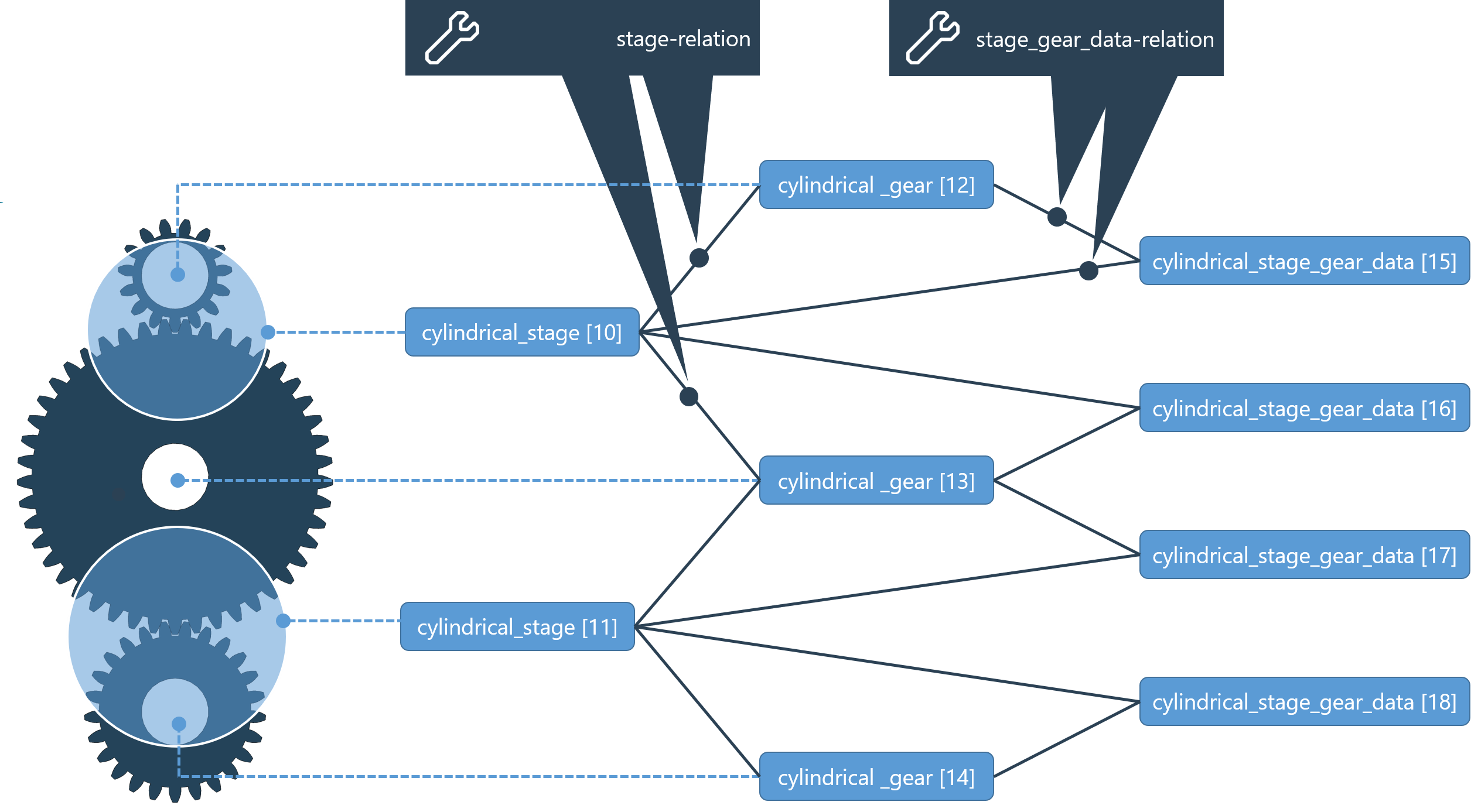
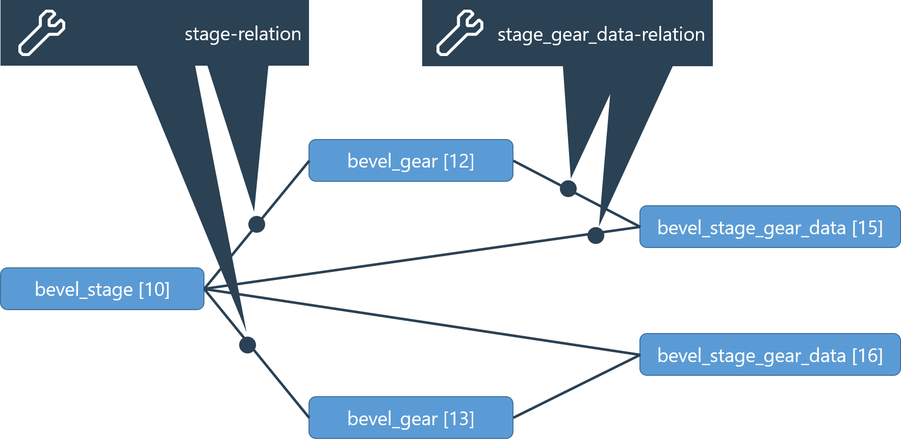
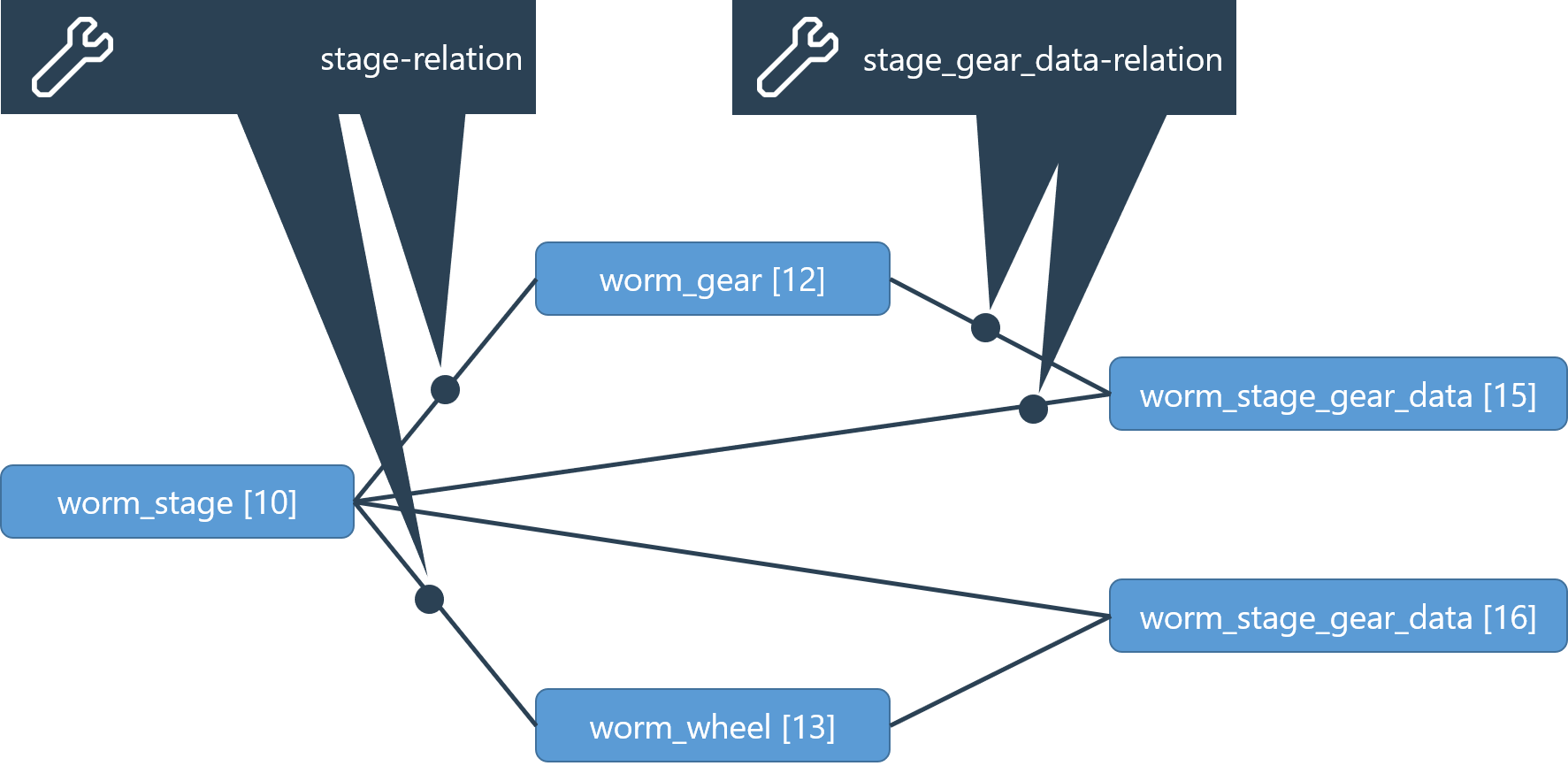
This mesh-related gear data is represented in the virtual stage_gear_data component. For each stage and gear there is a stage_gear_data component that is associated with the stage-gear combination.
Through REXS 1.2, a generic stage_gear_data component was used for all gear types. Starting with REXS version 1.3, the following specific components are used for the different gear types:
cylindrical_stage: cylindrical_stage_gear_data
bevel_stage: bevel_stage_gear_data
worm_stage: worm_stage_gear_data
As the basic principle and the relations used are the same, the generic stage_gear_datacomponent is used in the following example.
Required components | XML Syntax |
|---|---|
general_stage | <component id="10" type="general_stage"> ... </component> |
general_gear | <component id="12" type="general_gear"> ... </component> |
stage_gear_data | <component id="15" type="stage_gear_data"> ... </component> |
Required relations | XML syntax |
|---|---|
stage_gear_data relation Stage - gear - stage gear data | <relation id="2" type="stage_gear_data"> <ref id="10" role="stage" hint="general_stage"/> <ref id="12" role="gear" hint="general_gear"/> <ref id="15" role="stage_gear_data" hint="stage_gear_data"/> </relation> |
Gears and flanks
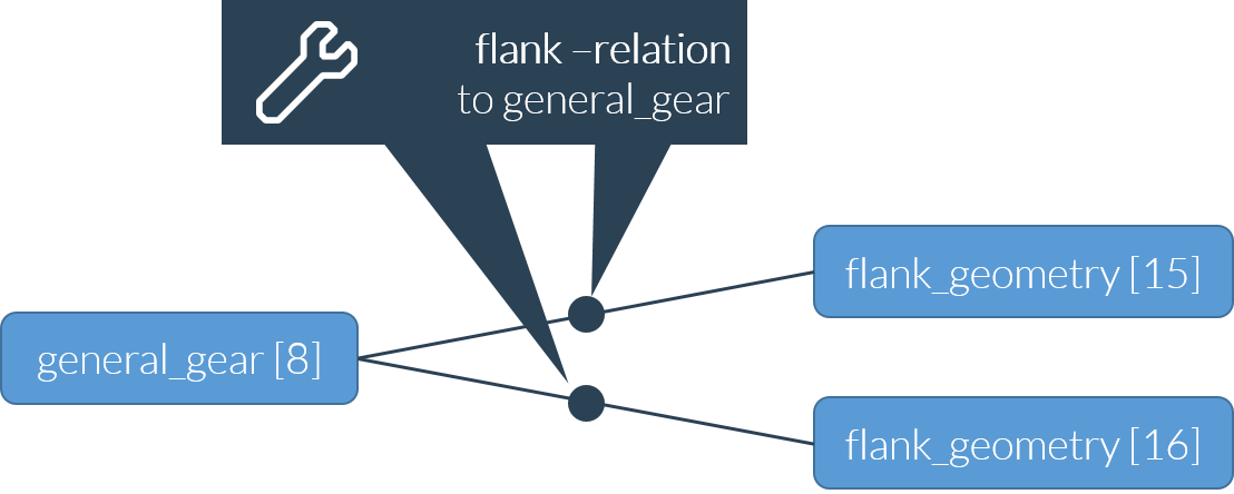
To enable the assignment of gear tooth flank data, two flank components (left and right) are assigned to each gear (general_gear) via flank relations. The viewing direction must be individually specified for each gear type.
cylindrical_gear: viewing direction is from the datum face of the gear towards the non-datum face
bevel_gear: viewing direction is from the cone tip toward the gear
worm_gear: viewing direction is along the u-axis of the gear
worm_wheel: viewing direction is along the u-axis of the gear
The right flank (or left flank) is the flank seen on the right (or left) side in the viewing direction of an upward pointing tooth (see ISO 21771 or DIN 3960). If necessary, modeling of the individual teeth of the gear can be supplemented at a later date.
Through REXS 1.2, a generic flank_geometry component was used for all gear types. Starting with REXS version 1.3, the following specific components are used for the different gear types:
cylindrical_gear / ring_gear: cylindrical_gear_flank
bevel_gear: bevel_gear_flank
worm_gear / worm_wheel: worm_gear_flank
As the basic principle and the relations used are the same, the generic flank_geometry component is used in the following example.
Required components | XML syntax |
|---|---|
general_gear | <component id="8" type="general_gear"> ... </component> |
flank_geometry | <component id="15" type="flank_geometry"> ... </component> |
flank_geometry | <component id="16" type="flank_geometry"> ... </component> |
Required relations | XML syntax |
|---|---|
Flank relation Gear-flank-flank | <relation id="2" type="flank">"> <ref id="8" role="gear" hint="general_gear"/> <ref id="15" role="left" hint="flank_geometry"/> <ref id="16" role="right" hint="flank_geometry"/> </relation> |
Example - model of a gear with right and left flanks
Flank modifications and flank deviations
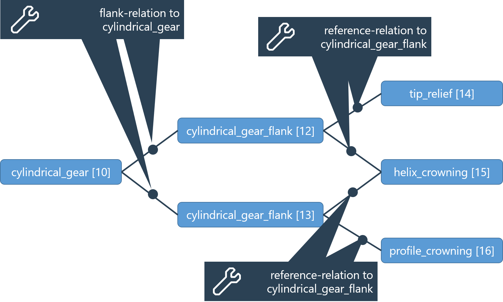
Flank modifications and flank deviations can be assigned to the flanks of a cylindrical gear to enable a detailed description of the tooth flank shape of cylindrical gears.
Each type of modification is represented by its own component type (e.g.,"tip_relief")
Any number of modifications and deviations can be assigned to a tooth flank using "reference" relations.
Multiple tooth flanks can reference a flank modification (e.g., if the right and left flanks receive the same modification).
Example - model of a gear with right and left flanks and multiple flank modifications
Overview of the various standard flank modifications:
Profile angle modification (profile_slope)
Tip relief (tip_relief)
Root relief (root_relief)
Profile crowning (profile_crowning)
Helix crowning (helix_crowning)
Helix slope modification (helix_slope)
Datum face end relief (end_relief_datum_face)
Non-datum face end relief (end_relief_non_datum_face)
Topographical flank modification (topographical_modification)
Triangular tip relief (triangular_tip_relief)
Triangular root relief (triangular_root_relief)
Profile twist (profile_twist)
Overview of various flank deviations:
Profile deviation (profile_deviation)
Helix deviation (helix_deviation)
Topographic deviation of the tooth flank can be specified via the corresponding attribute of the flank_geometry component.
Required components | XML syntax |
|---|---|
cylindrical_gear_flank | <component id="15" type="cylindrical_gear_flank"> ... </component> |
flank_modification/flank_deviation | <component id="17" type="tip_relief"> ... </component> |
Required relations | XML syntax |
|---|---|
Reference relation to the flank | <relation id="2" type="reference">" <ref id="15" role="origin" hint="cylindrical_gear_flank"/> <ref id="17" role="referenced" hint="tip_relief"/> </relation> |
Tools and manufacturing settings
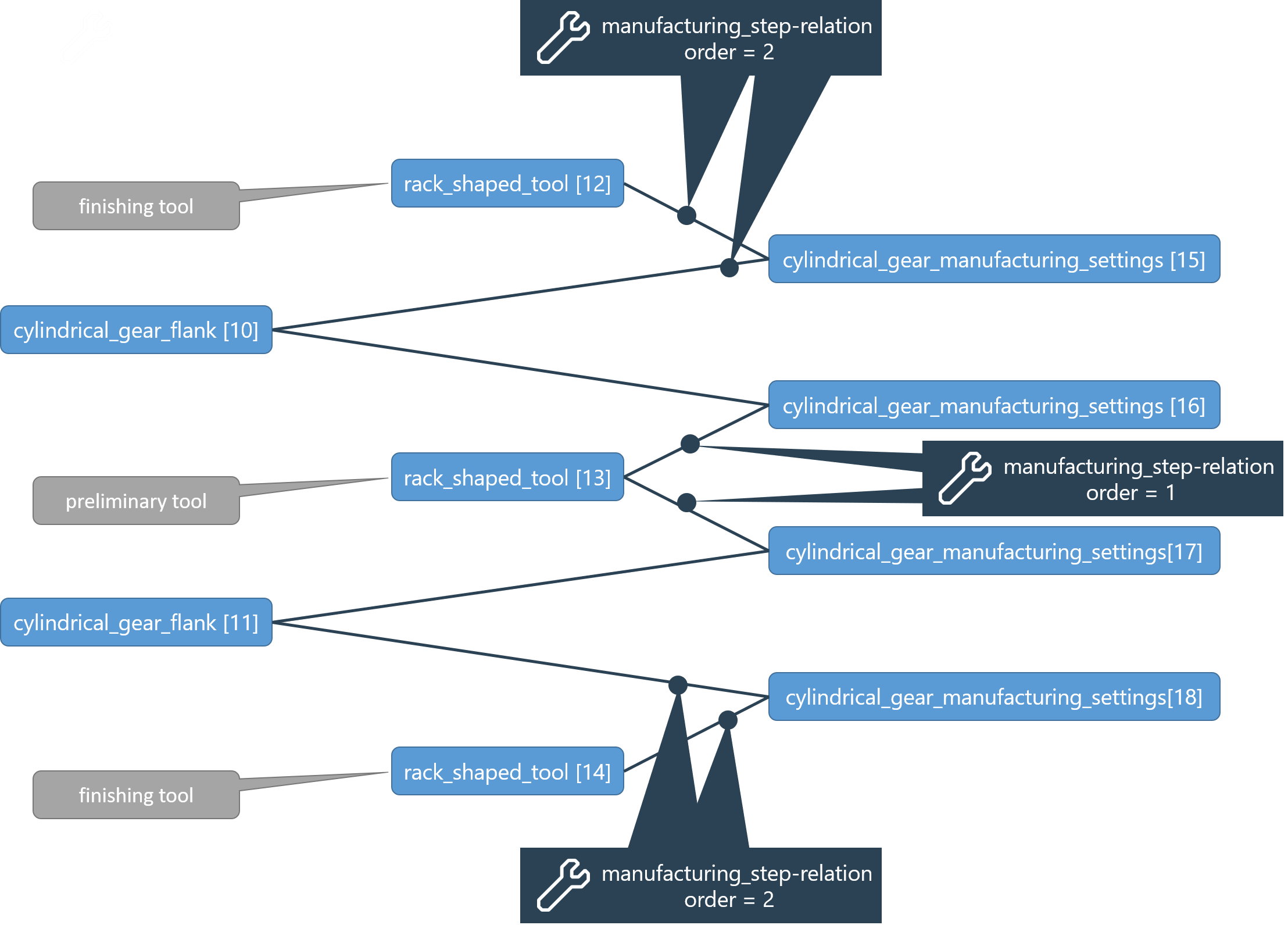
A gear can be generated by machining with multiple tools. If necessary, the left and right flank of a gear can be machined with different tools. Finally, some manufacturing settings (such as the machining allowance for cylindrical gears) are critical for the manufacturing results. To model these relationships, a tooth flank processing step is represented by a manufacturing_step relation which connects a tooth flank, the tool, and the associated manufacturing settings.
Appropriate components for the gear type should be used:
Gear type | Flank | Tool | Manufacturing settings |
|---|---|---|---|
cylindrical_gear | cylindrical_gear_flank | rack_shaped_tool cutter_wheel_tool zero_degree_grinding_disk_tool | cylindrical_gear_manufacturing_settings |
ring_gear | cylindrical_gear_flank | cutter_wheel_tool | cylindrical_gear_manufacturing_settings |
bevel_gear | bevel_gear_flank | bevel_gear_tool | bevel_gear_manufacturing_settings |
worm_gear | worm_gear_flank | worm_grinding_disc_tool | worm_gear_manufacturing_settings |
worm_wheel | worm_gear_flank | worm_wheel_hob_tool | worm_gear_manufacturing_settings |
For a bevel gear, the bevel_gear_tool corresponds to the cutter, and bevel_gear_manufacturing_settings corresponds to the machine settings.
Example for 2 manufacturing_step relations for a cylindrical gear flank:
Required relations | XML syntax |
|---|---|
manufacturing_step order 1 | <relation id="3" type="manufacturing_step" order="1"> <ref id="3" role="workpiece" hint="cylindrical_gear_flank"/> <ref id="15" role="tool" hint="cutter_wheel_tool"/> <ref id="18" role="manufacturing_settings" hint="cylindrical_gear_manufacturing_settings"/> </relation> |
manufacturing_step order 2 | <relation id="4" type="manufacturing_step" order="2"> <ref id="3" role="workpiece" hint="cylindrical_gear_flank"/> <ref id="16" role="tool" hint="rack_shaped_tool"/> <ref id="19" role="manufacturing_settings" hint="cylindrical_gear_manufacturing_settings"/> </relation> |