Notches
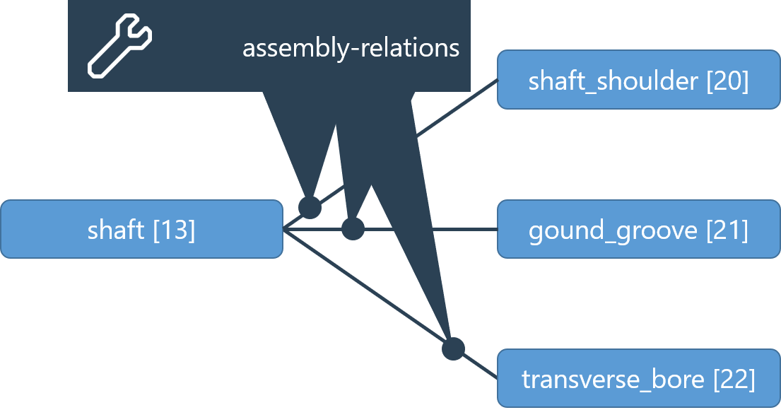
Shaft geometry can now be described with additional detail by modeling so-called notches. This includes shaft shoulders, which more precisely describe the transition from one shaft section to the next. They can also describe round and rectangular grooves, v-notches, and transverse bores. Each of these notch shapes is available as an independent component type with corresponding parameters. Notches are connected to the associated shaft via an assembly relation. A notch can only be assigned to one shaft. However, a shaft can include several notches.
Overview of available notch types:
Shaft shoulder (shaft_shoulder)
Shaft shoulder with undercut (shaft_shoulder_with_undercut)
Round groove (round_groove)
Rectangular groove (rectangular_groove)
V-notch (v_notch)
Transverse bore (transverse_bore)
Shaft-hub connections can also act as notches, see Notch calculation for shaft-hub connections.
Required components | XML syntax |
|---|---|
Shaft | <component id="3" type="shaft"> ... </component> |
Notch | <component id="113" type="shaft_shoulder"> ... </component> |
Required relations | XML syntax |
|---|---|
Assembly relation Shaft - notch | <relation id="175" type="assembly"> <ref id="3" role="assembly" hint="shaft"/> <ref id="113" role="part" hint="shaft_shoulder"/> </relation> |

Notches are positioned via the shaft coordinate system. In general, the position ("u_coordinate_on_shaft" attribute) of a notch refers to its "beginning;" i.e., to the location of the notch with the smallest u-coordinate in the shaft coordinate system. However, for shaft shoulders, the position of the notch corresponds to the position of the shoulder (the transition point of the underlying shaft sections). Therefore, for a shaft shoulder of small-to-large diameter, the position of the notch corresponds to the "end of the notch."
