Shaft-Hub Connections
Through REXS 1.3, shaft-gear connections in REXS could only be identified by assembly relations between these two components. Shaft-shaft connections can be made with abstract couplings or abstract switchable couplings via a side relation.

Modeling of connections up to REXS version 1.3
These modeling options are still available. However, from REXS 1.4, these connections can also be modeled more accurately. Several different shaft-hub connections are available:
Cylindrical interference fits (cylindrical_interference_fit)
Tapered interference fits (tapered_interference_fit)
Tapered interference fits (tapered_interference_fit)
Involute spline connections (involute_spline_connection)
Additional designs will be added at a later date.
The individual designs are described in more detail below. First, however, the general use of shaft-hub connections in the model will be explained.
A shaft-gear connection is created via a side relation of the shaft-hub connection with the shaft and the gear. In this case, the assembly relation between the gear and shaft is omitted.
A shaft-shaft connection is created via a side-relation of the shaft-hub connection with both shafts. The abstract coupling Couplings component is replaced by the shaft-hub connection component. The shaft-hub connection includes all relevant attributes of the coupling (e.g., stiffness, reaction forces and moments, etc.)
Additional connections for which a Couplings component can be used (e.g., Side plates | side_plate) can also be created via a shaft-hub connection.

Modeling of connections from REXS version 1.4
Interference fits
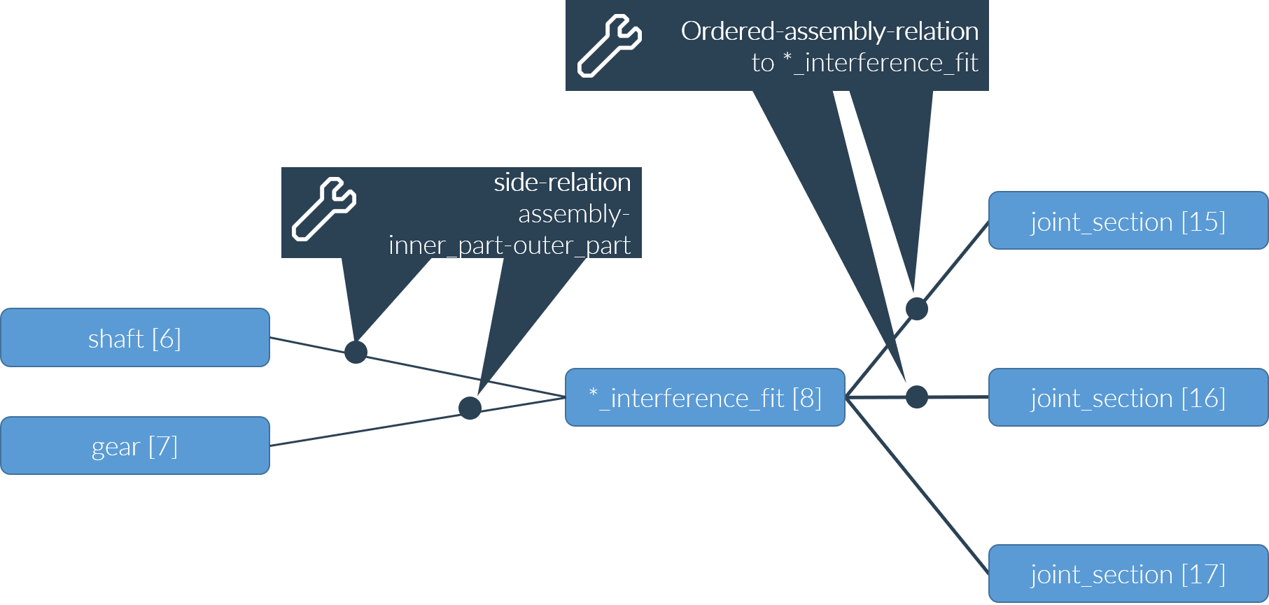
Cylindrical interference fits (cylindrical_interference_fit) and tapered interference fits (tapered_interference_fit) can be used. In accordance with DIN 7190, these can consist of multiple joint sections with different diameters. For interference fits with multiple axial joint sections, the joint is divided into slices with a constant diameter along the shaft axis (see DIN 7190-2 section 4.4). In REXS, these slices are identified as joint sections (joint_section). A single joint section can be used for simple interference fits where the relevant diameter is constant along the entire joint length. Interference fits with multiple axial joint sections and multiple interference fits can also be modeled. Here, one or more sleeves are pressed in between the shaft/inner side and hub/outer side. These sleeves are not represented as separate components, they are described by the diameters and lengths of the joint sections.
The individual joint sections are assigned to the interference fit via ordered_assembly relations. The "order" of the relations specifies their sequence in the axial direction for an interference fit with multiple joint sections, or in the radial direction for a multiple interference fit. In the special case of a multiple interference fit with a stepped hub, the order is specified in the radial direction; for sections with an equal diameter, the order is specified in the axial direction.

Required components | XML syntax |
|---|---|
cylindrical_interference_fit tapered_interference_fit | <component id="8" type="*_interference_fit"> ... </component> |
shaft | <component id="6" type="shaft"> ... </component> |
gear / outer shaft | <component id="7" type="*_gear"> ... </component> / <component id="7" type="shaft"> ... </component> |
joint_section_1 | <component id="15" type="joint_section"> ... </component> |
joint_section_m | <component id="17" type="joint_section"> ... </component> |
Required relations | XML syntax |
|---|---|
Side relation *_interference_fit – shaft – gear | <relation id="1" type="side"> <ref id="8" role="assembly" hint="*_interference_fit"/> <ref id="6" role="inner_part" hint="shaft"/> <ref id="7" role="outer_part" hint="*_gear"/> </relation> |
Ordered assembly relation *_interference_fit – joint_section order 1 | <relation id="4" type="ordered_assembly" order="1"> <ref id="8" role="assembly" hint="*_interference_fit"/> <ref id="15" role="part" hint="joint_section"/> </relation> |
Ordered assembly relation *_interference_fit – joint_section order 2 | <relation id="5" type="ordered_assembly" order="2"> <ref id="8" role="assembly" hint="*_interference_fit"/> <ref id="16" role="part" hint="joint_section"/> </relation> |
Feather key connections
Feather key connections can be represented via the feather_key_connection component. The feather key and the grooves in the shaft and hub are not represented by components; the relevant parameters according to DIN 6885 and DIN 6892 are specified on the feather key connection component.
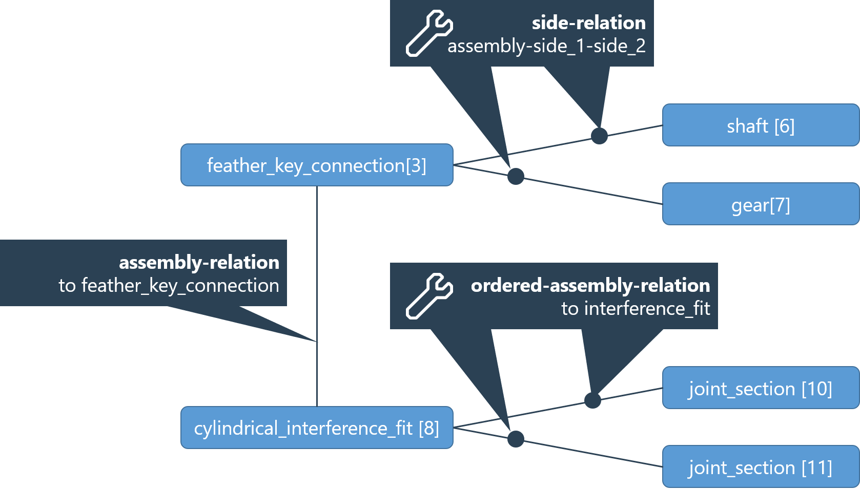
Feather key connections are often combined with an additional interference fit of the hub on the shaft. In these cases, the feather key connection is modeled as the parent shaft-hub connection, which connects the shaft and hub via a side-relation. The cylindrical or tapered interference fit is assigned to the feather key connection via an assembly relation.
A material can be assigned to the feather key connection component as a substitute for the feather key. The materials for the shaft and hub are assigned directly to the corresponding components, as usual.

Required components | XML syntax |
|---|---|
feather_key_connection | <component id="5" type="feather_key_connection"> ... </component> |
shaft | <component id="6" type="shaft"> ... </component> |
gear/outer shaft | <component id="7" type="*_gear"> ... </component> / <component id="7" type="shaft"> ... </component> |
Optional components | XML syntax |
|---|---|
cylindrical_interference_fit tapered_interference_fit | <component id="8" type="*_interference_fit"> ... </component> |
joint_section_1 | <component id="10" type="joint_section"> ... </component> |
joint_section_m | <component id="11" type="joint_section"> ... </component> |
Required relations | XML syntax |
|---|---|
Assembly relation | <relation id="4" type="assembly" > <ref id="5" role="assembly" hint="feather_key_connection"/> <ref id="8" role="part" hint="*_interference_fit"/> </relation> |
Assembly relation | <relation id="5" type="assembly"> <ref id="8" role="assembly" hint="*_interference_fit"/> <ref id="10" role="part" hint="joint_section"/> </relation> |
Involute spline connections
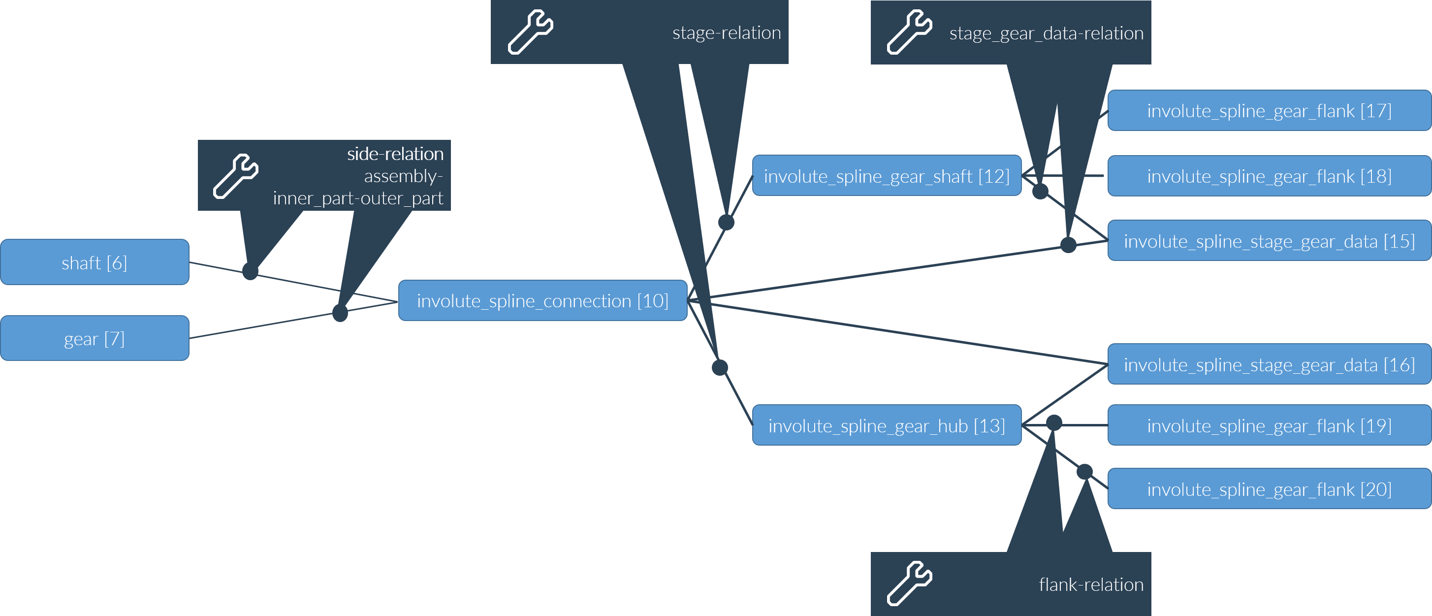
The geometry of involute spline connections is addressed in ISO 4156, DIN 5480, DIN 5466, and others. Involute spline connections are modeled in REXS similar to (involute) cylindrical gears. A spline connection consists of the involute_spline_connection "stage" component and the two "gears," involute_spline_gear_shaft and involute_spline_gear_hub. Furthermore, every gear includes two involute_spline_gear_flank components, and the stage has an involute_spline_stage_gear_data component for each gear. Flank modifications/deviations can be specified along with manufacturing data and tools.
The specifications in the following sections apply accordingly: Gear types, Mesh-related gear data, Gears and flanks, and Tools and manufacturing settings. For spline connections, assembly relations between the shaft/hub and the involute_spline_gears and between the gear_unit and the involute_spline_connection are omitted. As with all shaft-hub connections, the connection between the shaft and hub is represented by a side-relation with the involute_spline_connection.

Notch calculation for shaft-hub connections
Shaft-hub connections weaken the (inner) shaft; for example, they are calculated as notches in DIN 743. The notch effect is strongest at the beginning and end of the shaft-hub connection. The relevant parameters can be stored in the "notch effect of shaft-hub connection" component (notch_effect_shaft_hub_connection). One or more of these components can be assigned to shaft-hub connections via assembly relations. The notch calculation position can be marked via a corresponding attribute of the notch_effect_shaft_hub_connection.
Special case: For spline gears, the "notch effect of the shaft-hub connection" component is assigned to the involute_spline_gear_shaft component.
Required components | XML syntax |
|---|---|
shaft-hub-connection involute_spline_gear_shaft | <component id="5" type="shaft_hub_connection"> ... </component> <component id="9" type="involute_spline_gear_shaft"> ... </component> |
notch_effect_shaft_hub_connection 1 | <component id="16" type="notch_effect_shaft_hub_connection"> ... </component> |
notch_effect_shaft_hub_connection 2 | <component id="17" type="notch_effect_shaft_hub_connection"> ... </component> |
Required relations | XML syntax |
|---|---|
Assembly relation | <relation id="4" type="assembly" > <ref id="5" role="assembly" hint="shaft_hub_connection"/> <ref id="16" role="part" hint="notch_effect_shaft_hub_connection"/> </relation> |
Assembly relation | <relation id="5" type="assembly"> <ref id="5" role="assembly" hint="shaft_hub_connection"/> <ref id="17" role="part" hint="notch_effect_shaft_hub_connection"/> </relation> |